الاثنين، 14 مارس 2016

نتسائل كثيرا DC or AC و AC or DC ????

بواسطة : mourad بتاريخ : 4:43 م

سنحاول الوصول الى نتائج و النظر فى مزايا و عيوب كل جزء …..
فما هو الافضل بنقل الطاقه
اليكم التالى :-
أولا:

طرق النقل بصورة AC
– ان طرق توليد التيار المتردد ذات القدرة العالية جدا اقل صعوبة وتعقيد من توليد القدرة بصورة DC
– تحويل مستويات الجهد المتردد يكون بصورة سهلة باستخدام المحولات ولكن في حالة التيار المستمر يكون صعب ويحتاج لتكنولوجيا الكترونيات القدرة
– ان رفع الجهد لمستويات عالية جدا وخفض التيار يمكننا من نقل كمية كبيرة من الطاقة عبر اسلاك اقل سمكا .. ومسافة اكبر بدرجة فقد اقل
– طريقة تحويل التيار المتردد لتيار مستمر سهلة جدا جدا باستخدام الدايودات والقناطر
– بعض المحركات والمعدات تعمل على تيار متردد ويكون عزمها اكبر في هذه الحالة من استبدالها بمحركات تيار مستمر
– يعتبر التيار المتردد اكثر امانا من التيار المستمر ذو نفس الجهد … وذلك لانه التيار المتردد يصل للصفر خلال الدورة الواحدة مرتين ممكن يفتح أملا في النجاة .. ولكن التيار المستمر يكون عند الحالة العليا دائما …
– بسبب التردد الذي يخلق ظاهرة (Skin effect) ويجعل التيار يسير على سطح السلك فقط اضطروا لصنع اسلاك ذات اكثر من قلب (Multicore)
– يحتاج لعدد اسلاك اكبر (3 phase)

ثانيا:

طرق النقل بصورة DC
– لا يحتاج النقل الا لسلكين اثنين فقط
– تكلفة الاسلاك هنا اقل من حالة AC
– لا يحتاج ربط مصادر الجهد لعملية مزامنة مثل مولدات AC … فهنا عملية الربط اسهل بكثير
– تأثير الحث للاسلاك على تخفيض الجهد هنا يختفي ولكن في حالة ال AC فان الحث يسبب مقاومة ومن ثم نقص الجهد قليلا مع المسافة
– لا وجود لظاهرة Skin effect
– عملية رفع وخفض الجهد صعبة ومكلفة
– لا يحتاج لعملية تصحيح power factor
– ليس هناك مشاكل في عدم استقرار النظام او مشاكل الرنين Resonance
في النهاية … ميزة سهولة التوليد ورفع وخفض الجهد والتحويل تتفوق في حالة AC عن ال DC …. ولكن من يدري لعل مع ازدياد نشاط مصادر الطاقة المتجددة واعتماد فكرة الشبكة الذكية (Smart Grid) وتوظيف منتجات الكترونيات القوى ( Power Electronics) يمكن أن تقلب الموازين وتجعل المستقبل للتيار المستمر DC.


كوريا الشمالية تنفي تنفذيها هجمات إلكترونية ضد كوريا الجنوبية

بواسطة : mourad بتاريخ : 4:34 م

نفت كوريا الشمالية يوم الاحد قيامها بهجمات الكترونية ضد مسؤولين من كوريا الجنوبية، واصفة اتهام كوريا الجنوبية لها بانه تلفيق، وذلك بحسب تقرير نشرته وكالة رويترز.
وأخبرت وكالة التجسس في كوريا الجنوبية النواب يوم الجمعة بان كوريا الشمالية قد صعدت مؤخراً جهودها فيما يخص الهجمات الالكترونية ضد الجنوب.
ونجحت في اختراق الهواتف المحمولة التابعة لـ 40 مسؤولاً للأمن القومي، وذلك وفقاً لأعضاء البرلمان الذين تواجدوا في الجلسة المغلقة.
وقالت صحيفة رودونغ سينمون الصحيفة اليومية الرسمية للحزب الحاكم في كوريا الشمالية يوم الاحد في مقال رأي “إن الجنوب يدعي تنفيذ كوريا الشمالية هجوم عبر الانترنت، وتقوم كوريا الجنوبية باستخدام هذا الادعاء لأغراض سياسية خاصة بها”.
وأضافت الصحيفة أن كوريا الجنوبية أطلقت هذا الادعاء فيما يخص الهجوم عبر الإنترنت من أجل تبرير قانون مكافحة الإرهاب الجديد والمثير للجدل.
وقال جهاز المخابرات الوطني في كوريا الجنوبية خلال وقت سابق من هذا الاسبوع بان كوريا الشمالية حاولت الوصول إلى حسابات البريد الإلكتروني لعمال سكك الحديد في كوريا الجنوبية.
ويأتي الهجوم على حسابات البريد في محاولة منها لمهاجمة نظام التحكم في النقل، وأضاف جهاز المخابرات بانه اوقف هذا الهجوم ضد عمال سكك الحديد، وتم إغلاق حسابات البريد الإلكتروني التابعة لهم.
وتضع كوريا الجنوبية نفسها في حالة تأهب قصوى لصد خطر الهجمات الإلكترونية التي تنفذها كوريا الشمالية بعد أن أجرت تجربة نووية في يناير، واطلاقها صاروخ بعيد المدى الشهر الماضي، مما عرضها لعقوبات جديدة من الأمم المتحدة.
كما نفت كوريا الشمالية الاتهامات الكورية الجنوبية السابقة حول تنفذها هجمات إلكترونية ضد المشغل النووي الكوري الجنوبي.
وكانت الولايات المتحدة قد اتهمت كوريا الشمالية في عام 2014 بتنفيذ هجوم الكتروني ضد شركة سوني بيكتشرز، مما أجبر الشركة على وقف عرض الفيلم الكوميدي الذي يسخر من الرئيس الكوري الشمالي كيم جونغ ون.

الخميس، 18 فبراير 2016

Arduino & Raspberry Pi Camera Interface

بواسطة : mourad بتاريخ : 2:38 م
Yes,we learned that we can take mobile phone camera modules from almost all mobile phones to inteface them with our advanced hobby electronics projects just as with any other standard add-on modules. Since this calls for an appropriate microcontroller, it is better to use Arduino or Raspberry Pi microcontroller as a utile platform.
Raspberry Pi camera
Recently I’ve received a Raspberry Pi camera board. The camera, comes with a ribbon cable already attached to it,is a small size (25mm x 20mm x 9mm) board where a fixed focus 5MP camera module is attached. Part number of the camera module (from OmniVision) is OV5647. At the heart of the OV5647 camera module is a 1/4” color CMOS QSXGA (5 megapixel) image sensor with OmniBSI ™ technology. This Raspberry Pi camera module can be used to take high definition video, as well as stills photographs. It is easy to use for novices, but has plenty to offer advanced users looking to expand the knowledge.
raspberry pi camera
(raspberry pi camera)
Raspberry PI comes with two first-rate connectors on board. One is between Ethernet and HDMI, and the other is near GPIO. The one closer to Ethernet connector is Camera Serial Interface (CSI ). This CSI is directly connected to the Raspberry Pi GPU which can process images without ARM intervention.
Camera Serial Interface
(Camera Serial Interface)
While connecting the camera module to the CSI port (located behind the Ethernet port) of the Raspberry Pi board,ensure that camera cable is inserted in right way, ie the blue strip in the flexible cable is towards the Ethernet (LAN) port. Once you are connected,enable the camera software, test the camera and try using it with Bash or Python. As I am a newbie in the Raspberry Pi world, I haven’t drudged enough into all features and capabilities of my borrowed Raspberry Pi (and the camera module). If you want to leap into the future of amazing possibilities, have a look at the documentation: http://www.raspberrypi.org/help/camera-module-setup/
The Raspberry Pi camera board transfers data through an extremely fast camera serial interface (CSI-2) bus directly to the system-on-chip (SoC) processor. It does this through a 15-pin ribbon cable, also known as flexible flat cable (FFC), and connects to the surface mount ZIF 15 socket in the Raspberry Pi board. As you may noted, the camera module on this official Raspberry Pi camera board is identical to the camera modules (ccd imagers) found in many mobile phones.
camera  data transmission interface
Luckily, most of the mobile phone cameras are not only MIPI compliant but also CSI compliant (see the first part of this article). The 15-pin Raspberry Pi CSI interface connector pinout is also included here to help you to keep proceed with your tinkering ideas. Note that, in Raspberry Pi, there are two flexible Flat Cable (FFC) connectors (S2 & S5). S2, near to the micro USB connector, is the Display Serial Interface (DSI). It allows low-level interfacing with LCDs and other displays with Raspberry Pi. It is a 15-pin surface mounted flexible flat connector, providing two data lanes, one clock lane, 3.3V and GND. S5, located between LAN and HDMI connector is the MIPI Camera Serial Interface 2 (CSI-2) connector for camera modules. It is a 15-pin surface mounted flat flexible connector, providing two data lines, one clock lane, bidirectional control interface compatible with I2C, 3.3V and GND. The data transmission interface in CSI is unidirectional differential serial interface with data and clock signals (the physical layer of this interface is the MIPI Alliance Standard for DPHY).
Arduino camera
Adding a camera to your Arduino UNO is not very difficult, because ArduCAM ™ Shield is infront of you. You can find a good tutorial on ArduCAM here: http://www.arducam.com/tutorial/. This tutorial will demonstrate how to use the ArduCAM shield on Arduino UNO board, aim the point and press a snapshot button you will get a BMP picture saved on the SD/TF card!
arduino camera arducam
ArduCAM shield hardware integrates all the necessary components to interface with camera modules. User only need a extra support camera modules and a TF/SD card to start image capture. The ArduCAM shield includes a ArduChip which handle complex timing between MCU and LCD, Camera, FIFO. It exports a standard SPI serial interface and can be interfaced with wide range of microcontrollers. Further, ArduCAM shield includes two sets of pin out, identical in function. One is Arduino standard, it can be well mate with standard Arduino boards like UNO, MEGA2560, Leonardo and DUE etc. The other one is alternative port which can be connect to any platform like Raspberry Pi. After the great success of ArduCAM shield Rev.B, the ArduCAM team now released a more powerful ArduCAM shield Rev.C with amazing new features. This revision supports camera modules including OV7660, OV7670, OV7675, OV7725, OV2640, OV3640, OV5642 and MT9D111.
(Tinker Hint: 16-pin camera connector in Nokia mobile phone 7380)
Did You Know? CMOS image sensor interface divided into two classes, one is DVP (Digital Video Port) interface, the other is MIPI Mobile Industry Processor Interface. The main difference between DVP and MIPI is that DVP is parallel interface and the MIPI interface is high speed differential serial interface. MIPI interface provide higher data band width than DVP interface and support higher resolution and frame rate.
camera modules
Image sensor is usually cheap and you can buy them for as little as $5.00 on eBay. However, when it turn into a “microcontroller-compatible camera module”, the finished board costs a lot more. In conclusion, I would have to say that it is worth spending time and effort to make your own camera modules, because the experience of reverse engineering and hacking is really interesting (at least for me). This is just a starting point, as promised I will come back with useful updates in near-future!

Summing amplifier using opamp.

بواسطة : mourad بتاريخ : 2:37 م

Summing amplifier using opamp.

Summing amplifier is a type operational amplifier circuit which can be used to sum signals. The sum of the input signal is amplified by a certain factor and made available at the output .Any number of input signal can be summed using an opamp. The circuit shown below is a three input summing amplifier in the inverting mode.
opamp summing amplifier
Summing amplifier circuit
In the circuit, the input signals Va,Vb,Vc are applied to the inverting input of the opamp through input resistors Ra,Rb,Rc. Any number of input signals can be applied to the inverting input in the above manner. Rf is the feedback resistor.Non inverting input of the opamp is grounded using resistor Rm. RL is the load resistor. By applying kirchhoff’s current law at not V2 we get,
Ia+Ib+Ic = If+Ib
Since the input resistance of an ideal opamp is close to infinity and has infinite gain. We can neglect Ib & V2
There for Ia+Ib+Ic = If ……….(1)
Equation (1) can be rewritten as
(Va/Ra) + (Vb/Rb)+ (Vc/Rc) = (V2-Vo)/Rf
Neglecting Vo,
we get Va/Ra + Vb/Rb + Vc/Rc = -Vo/Rf
Vo = -Rf ((Va/Ra)+(Vb/Rb)+(Vc/Rc))
Vo = -((Rf/Ra )Va + (Rf/Rb) Vb + (Rf/Rc) Vc)……..(2)
If resistor Ra, Rb, Rc has same value ie; Ra=Rb=Rc=R, then equation (2) can be written as
Vo = -(Rf/R) x (Va + Vb +Vc)…………….(3)
If the values of Rf and R are made equal , then the equation becomes,
Vo = -(Va + Vb +Vc)
Averaging Circuit : An averaging circuit can be made from the above circuit by making the all input resistor equal in value ie; Ra = Rb = Rc  =R and the gain must be selected such that if there are m inputs, then Rf/R must be equal to 1/m.
Scaling amplifier :  In a scaling amplifier each input will be multiplied  by a different factor and then summed together. Scaling amplifier is also called a weighted amplifier. Here different values are chosen for Ra, Rb and Rc. The governing equation is  Vo = -((Rf/Ra )Va + (Rf/Rb) Vb + (Rf/Rc) Vc).
Summing amplifier in non inverting configuration.

summing amplifier non inverting configuration
Summing amplifier in non inverting configuration
A non inverting summing amplifier circuit with three inputs are shown above. The voltage inputs Va, Vb and Vc are applied to non inverting input of the opamp.  Rf is the feedback resistor. The output voltage of the circuit is governed by the equation;
Vo = (1+ (Rf/R1)) (( Va+Vb+Vc)/3)

Best 4 books in the world of Arduino

بواسطة : mourad بتاريخ : 2:30 م

Best 4 books in the world of Arduino

-1-

Practical Arduino Cool Projects for Open Source Hardware

https://drive.google.com/open?id=0B1HQ0B8hfRtBY2MtTmJEa3hsM3M&authuser=0

-2-

All about Arduino Simulation

https://drive.google.com/open?id=0B1HQ0B8hfRtBUUJybmVTRmJtZ0k&authuser=0

-3-

Arduino Workshop A Hands-On Introduction with 65 Projects

https://drive.google.com/open?id=0B1HQ0B8hfRtBY2p5YmdKR2dEbDQ&authuser=0

-4-

Make Basic Arduino Project

Feb 2014
https://drive.google.com/open?id=0B1HQ0B8hfRtBME1LNkZXel81aTA&authuser=0

الأحد، 7 فبراير 2016

National Robotics Challenge 2015

بواسطة : mourad بتاريخ : 4:08 م
Every year for over 20 years the National Robotics Challenge (NRC) in Marion, OH, has hosted teams from around the country in a range of competitions aimed at highlighting robotics education.
SparkFun has been in attendance since 2011, and has been a sponsor since 2012. In the past two years we’ve stepped up our presence and hosted competitions. This year we were the judges and hosts for three competitions between April 9-12.
alt text
A hacked data collector running a sumo robot
For our second year we ran an interactivity challenge that asks students to build an interface with data coming from a peripheral like LEGO, VEX, Arduino or a mobile device, and show it in a graphical interface such as Processing, Java, Python or an IoT channel. This year’s winner was an innovative EKG style data-logger that wrote values to a time-stamped sheet of paper.
This was the first year we hosted an Autonomous Vehicle Challenge based on the race that happens at SparkFun every year. We scaled the size of the course slightly, and despite very questionable rain and thunderstorms, we had nine teams compete with three teams completing the course. We saw a range of vehicles, from LEGO and Vex-based vehicles, to Arduino driven rigs that would have been right at home at our race in Boulder.
The highpoint was the team from Cedarville University with an elegant, non-GPS based solution that was reliable and performed very well.
alt text
Student starts practice run in the pouring rain
In addition, this year SparkFun ran an optional cryptography challenge. This challenge wasn’t advertised and students could participate on a “drop-in” basis. The challenge was centered around four XBee radio beacons that were hidden on-site at the event. Students were given XBee Explorers to access the hidden beacons. Through a series of radio channels that responded to specific radio “pings,” the hidden beacons would return four strings of encoded text. The students then had to decode the text and reconstruct the original message. Kenton Robotics from Kenton, OH, was the first team to finish, and through the course of the day, four teams finished the puzzle. The event was wildly popular and we look forward to running it again, both at NRC and in other locations.
The NRC has grown to be a tremendous resource and we look forward to it every year. If you think your students would be interested, more information about NRC can be found here.

What is an Arduino?

بواسطة : mourad بتاريخ : 4:04 م

Introduction

Arduino is an open-source platform used for building electronics projects. Arduino consists of both a physical programmable circuit board (often referred to as a microcontroller) and a piece of software, or IDE (Integrated Development Environment) that runs on your computer, used to write and upload computer code to the physical board.
The Arduino platform has become quite popular with people just starting out with electronics, and for good reason. Unlike most previous programmable circuit boards, the Arduino does not need a separate piece of hardware (called a programmer) in order to load new code onto the board – you can simply use a USB cable. Additionally, the Arduino IDE uses a simplified version of C++, making it easier to learn to program. Finally, Arduino provides a standard form factor that breaks out the functions of the micro-controller into a more accessible package.
alt text
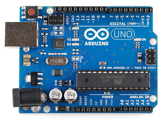
This is an Arduino Uno
The Uno is one of the more popular boards in the Arduino family and a great choice for beginners. We’ll talk about what’s on it and what it can do later in the tutorial.
Arduino Uno
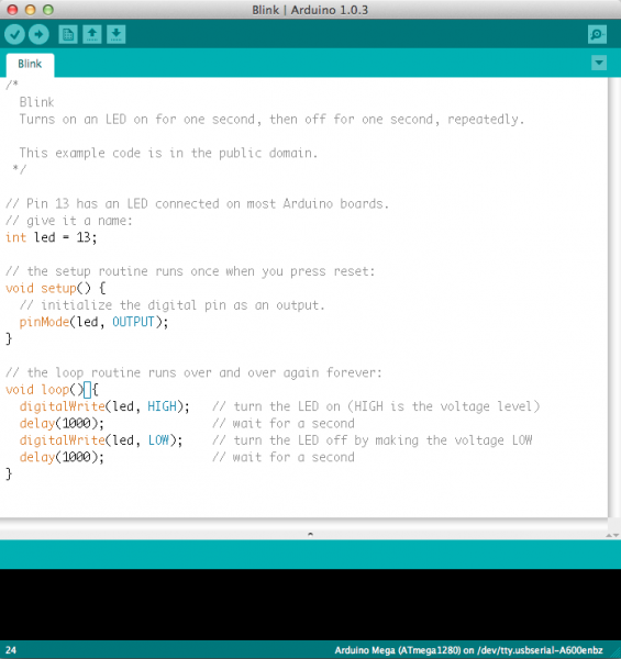
This is a screenshot of the Arduino IDE.
Believe it or not, those 10 lines of code are all you need to blink the on-board LED on your Arduino. The code might not make perfect sense right now, but, after reading this tutorial and the many more Arduino tutorials waiting for you on our site, we’ll get you up to speed in no time!

You Will Learn

In this tutorial, we’ll go over the following:
  • What projects can be accomplished using an Arduino
  • What is on the typical Arduino board and why
  • The different varieties of Arduino boards
  • Some useful widgets to use with your Arduino

Suggested Reading

Arduino is a great tool for people of all skill levels. However, you will have a much better time learning along side your Arduino if you understand some basic fundamental electronics beforehand. We recommend that you have at least a decent understanding of these concepts before you dive in to the wonderful world of Arduino.

What Does it Do?

The Arduino hardware and software was designed for artists, designers, hobbyists, hackers, newbies, and anyone interested in creating interactive objects or environments. Arduino can interact with buttons, LEDs, motors, speakers, GPS units, cameras, the internet, and even your smart-phone or your TV! This flexibility combined with the fact that the Arduino software is free, the hardware boards are pretty cheap, and both the software and hardware are easy to learn has led to a large community of users who have contributed code and released instructions for a huge variety of Arduino-based projects.
For everything from robots and a heating pad hand warming blanket to honest fortune-telling machines, and even a Dungeons and Dragons dice-throwing gauntlet, the Arduino can be used as the brains behind almost any electronics project.
alt text
_Wear your nerd cred on your sleev… err, arm. _
And that’s really just the tip of the iceberg – if you’re curious about where to find more examples of Arduino projects in action, here are some good resources for Arduino-based projects to get your creative juices flowing:

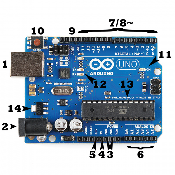
What's on the board?

There are many varieties of Arduino boards (explained on the next page) that can be used for different purposes. Some boards look a bit different from the one below, but most Arduinos have the majority of these components in common:
alt text

Power (USB / Barrel Jack)

Every Arduino board needs a way to be connected to a power source. The Arduino UNO can be powered from a USB cable coming from your computer or a wall power supply (like this) that is terminated in a barrel jack. In the picture above the USB connection is labeled (1) and the barrel jack is labeled (2).
The USB connection is also how you will load code onto your Arduino board. More on how to program with Arduino can be found in our Installing and Programming Arduino tutorial.
NOTE: Do NOT use a power supply greater than 20 Volts as you will overpower (and thereby destroy) your Arduino. The recommended voltage for most Arduino models is between 6 and 12 Volts.

Pins (5V, 3.3V, GND, Analog, Digital, PWM, AREF)

The pins on your Arduino are the places where you connect wires to construct a circuit (probably in conjuction with a breadboard and some wire. They usually have black plastic ‘headers’ that allow you to just plug a wire right into the board. The Arduino has several different kinds of pins, each of which is labeled on the board and used for different functions.
  • GND (3): Short for ‘Ground’. There are several GND pins on the Arduino, any of which can be used to ground your circuit.
  • 5V (4) & 3.3V (5): As you might guess, the 5V pin supplies 5 volts of power, and the 3.3V pin supplies 3.3 volts of power. Most of the simple components used with the Arduino run happily off of 5 or 3.3 volts.
  • Analog (6): The area of pins under the ‘Analog In’ label (A0 through A5 on the UNO) are Analog In pins. These pins can read the signal from an analog sensor (like a temperature sensor) and convert it into a digital value that we can read.
  • Digital (7): Across from the analog pins are the digital pins (0 through 13 on the UNO). These pins can be used for both digital input (like telling if a button is pushed) and digital output (like powering an LED).
  • PWM (8): You may have noticed the tilde (~) next to some of the digital pins (3, 5, 6, 9, 10, and 11 on the UNO). These pins act as normal digital pins, but can also be used for something called Pulse-Width Modulation (PWM). We have a tutorial on PWM, but for now, think of these pins as being able to simulate analog output (like fading an LED in and out).
  • AREF (9): Stands for Analog Reference. Most of the time you can leave this pin alone. It is sometimes used to set an external reference voltage (between 0 and 5 Volts) as the upper limit for the analog input pins.

Reset Button

Just like the original Nintendo, the Arduino has a reset button (10). Pushing it will temporarily connect the reset pin to ground and restart any code that is loaded on the Arduino. This can be very useful if your code doesn’t repeat, but you want to test it multiple times. Unlike the original Nintendo however, blowing on the Arduino doesn’t usually fix any problems.

Power LED Indicator

Just beneath and to the right of the word “UNO” on your circuit board, there’s a tiny LED next to the word ‘ON’ (11). This LED should light up whenever you plug your Arduino into a power source. If this light doesn’t turn on, there’s a good chance something is wrong. Time to re-check your circuit!

TX RX LEDs

TX is short for transmit, RX is short for receive. These markings appear quite a bit in electronics to indicate the pins responsible for serial communication. In our case, there are two places on the Arduino UNO where TX and RX appear – once by digital pins 0 and 1, and a second time next to the TX and RX indicator LEDs (12). These LEDs will give us some nice visual indications whenever our Arduino is receiving or transmitting data (like when we’re loading a new program onto the board).

Main IC

The black thing with all the metal legs is an IC, or Integrated Circuit (13). Think of it as the brains of our Arduino. The main IC on the Arduino is slightly different from board type to board type, but is usually from the ATmega line of IC’s from the ATMEL company. This can be important, as you may need to know the IC type (along with your board type) before loading up a new program from the Arduino software. This information can usually be found in writing on the top side of the IC. If you want to know more about the difference between various IC’s, reading the datasheets is often a good idea.

Voltage Regulator

The voltage regulator (14) is not actually something you can (or should) interact with on the Arduino. But it is potentially useful to know that it is there and what it’s for. The voltage regulator does exactly what it says – it controls the amount of voltage that is let into the Arduino board. Think of it as a kind of gatekeeper; it will turn away an extra voltage that might harm the circuit. Of course, it has its limits, so don’t hook up your Arduino to anything greater than 20 volts.

The Arduino Family

Arduino makes several different boards, each with different capabilities. In addition, part of being open source hardware means that others can modify and produce derivatives of Arduino boards that provide even more form factors and functionality. If you’re not sure which one is right for your project, check this guide for some helpful hints. Here are a few options that are well-suited to someone new to the world of Arduino:

Arduino Uno (R3)

The Uno is a great choice for your first Arduino. It’s got everything you need to get started, and nothing you don’t. It has 14 digital input/output pins (of which 6 can be used as PWM outputs), 6 analog inputs, a USB connection, a power jack, a reset button and more. It contains everything needed to support the microcontroller; simply connect it to a computer with a USB cable or power it with a AC-to-DC adapter or battery to get started.
alt text

LilyPad Arduino

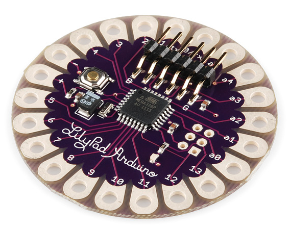
This is LilyPad Arduino main board! LilyPad is a wearable e-textile technology developed by Leah Buechley and cooperatively designed by Leah and SparkFun. Each LilyPad was creatively designed with large connecting pads and a flat back to allow them to be sewn into clothing with conductive thread. The LilyPad also has its own family of input, output, power, and sensor boards that are also built specifically for e-textiles. They’re even washable!
alt text

RedBoard

At SparkFun we use many Arduinos and we’re always looking for the simplest, most stable one. Each board is a bit different and no one board has everything we want – so we decided to make our own version that combines all our favorite features.
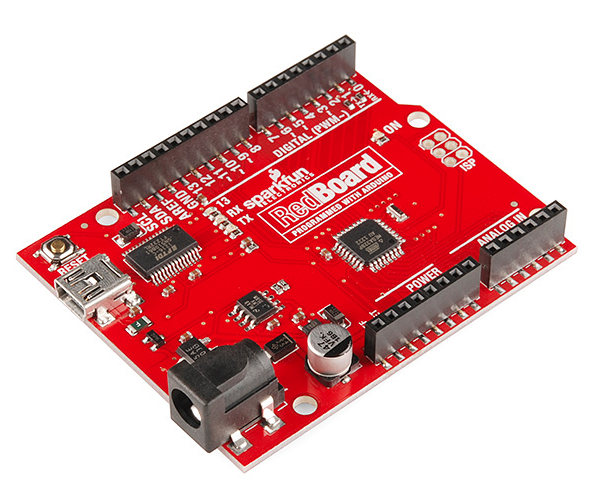
The RedBoard can be programmed over a USB Mini-B cable using the Arduino IDE. It’ll work on Windows 8 without having to change your security settings (we used signed drivers, unlike the UNO). It’s more stable due to the USB/FTDI chip we used, plus it’s completely flat on the back, making it easier to embed in your projects. Just plug in the board, select “Arduino UNO” from the board menu and you’re ready to upload code. You can power the RedBoard over USB or through the barrel jack. The on-board power regulator can handle anything from 7 to 15VDC.
alt text

Arduino Mega (R3)

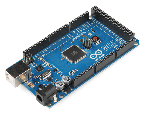
The Arduino Mega is like the UNO’s big brother. It has lots (54!) of digital input/output pins (14 can be used as PWM outputs), 16 analog inputs, a USB connection, a power jack, and a reset button. It contains everything needed to support the microcontroller; simply connect it to a computer with a USB cable or power it with a AC-to-DC adapter or battery to get started. The large number of pins make this board very handy for projects that require a bunch of digital inputs or outputs (like lots of LEDs or buttons).
alt text

Arduino Leonardo

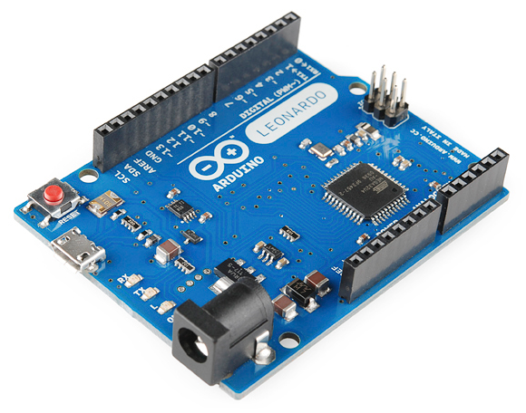
The Leonardo is Arduino’s first development board to use one microcontroller with built-in USB. This means that it can be cheaper and simpler. Also, because the board is handling USB directly, code libraries are available which allow the board to emulate a computer keyboard, mouse, and more!
alt text

The Extended Family

While your Arduino board sure is pretty, it can’t do a whole lot on its own – you’ve got to hook it up to something. There are lots of tutorials here on learn as well as the links back in the ‘What does it do’ section, but rarely do we talk about the general kinds of things you can easily hook into. In this section we’ll introduce basic sensors as well as Arduino shields, two of the most handy tools to use in bringing your projects to life.
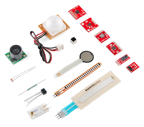
Sensors

With some simple code, the Arduino can control and interact with a wide variety of sensors - things that can measure light, temperature, degree of flex, pressure, proximity, acceleration, carbon monoxide, radioactivity, humidity, barometric pressure, you name it, you can sense it!
alt text
Just a few of the sensors that are easily compatible with Arduino

Shields

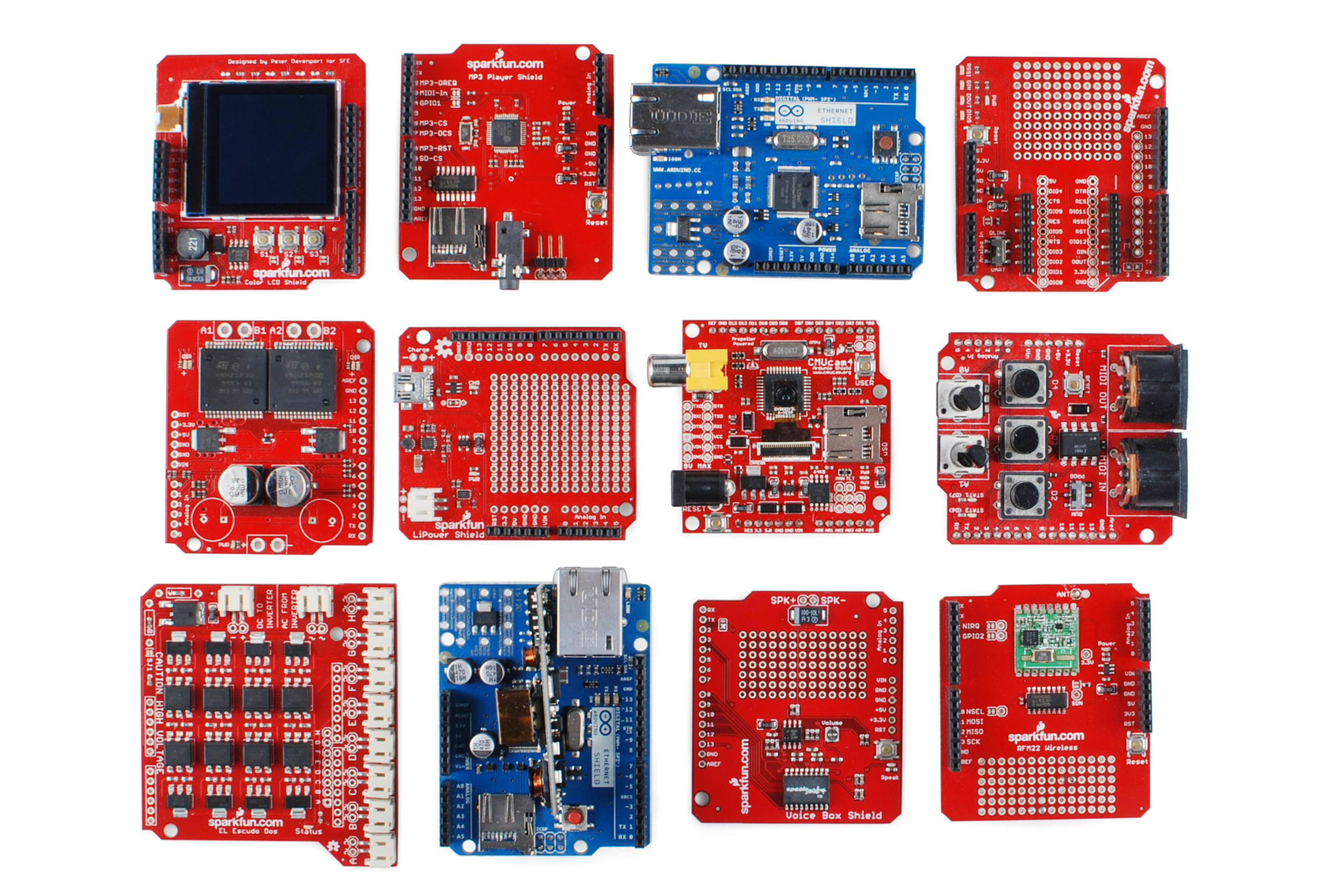
Additionally, there are these things called shields – basically they are pre-built circuit boards that fit on top of your Arduino and provide additional capabilities – controlling motors, connecting to the internet, providing cellular or other wireless communication, controlling an LCD screen, and much more.
alt text
A partial selection of available shields to extend the power of your Arduino
For more on shields, check out:

Resources and Going Further

For more info about the Arduino, check here and here.
Now that you know all about the Arduino family, which board you might want to use for your project, and that there are tons of sensors and shields to help take your projects to the next level. Here’s some further reading that may help you along in learning more about the world of electronics. For more info on Arduino, check out these tutorials:
For more hardware related tutorials, give these a read:

جميع الحقوق محفوضة لذى